The complete manual, online and always current: safety, commissioning, daily use, care, troubleshooting and specifications. Use the chapter menu to jump straight to what you need.
English is the authoritative language of this manual and of all Orthostand documentation. Translated versions are provided for convenience only; if a translation differs from the English version, the English version prevails.
Getting started with Orthostand M30
Dear Orthostand user,
You now have a tool that is designed to make your daily work physically sustainable. Working in bent, kneeling, or fixed positions places continuous strain on your back, neck, shoulders, and especially your knees. Over time, this builds up and can limit how long you can comfortably continue in your profession.
The Orthostand helps you work in a more natural, upright posture, reducing pressure on your joints and muscles while improving stability and control during treatment. Take the time to adjust it to your preferred working height and position, this is where the real benefit starts.
Use it consciously from the beginning. Your body will notice the difference, both today and in the years ahead.
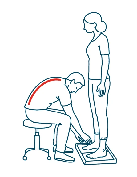
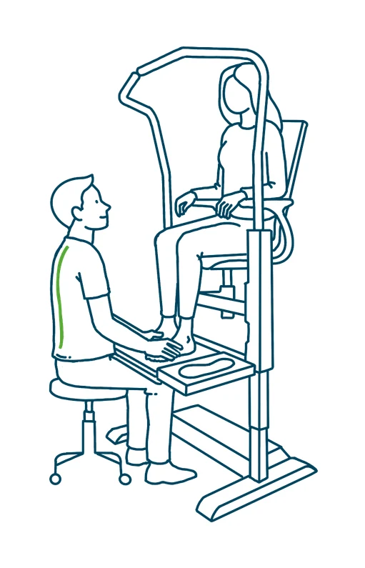
Without the Orthostand: bent, static posture that strains the back.With the Orthostand: the client is raised, the specialist stays upright.
Introduction
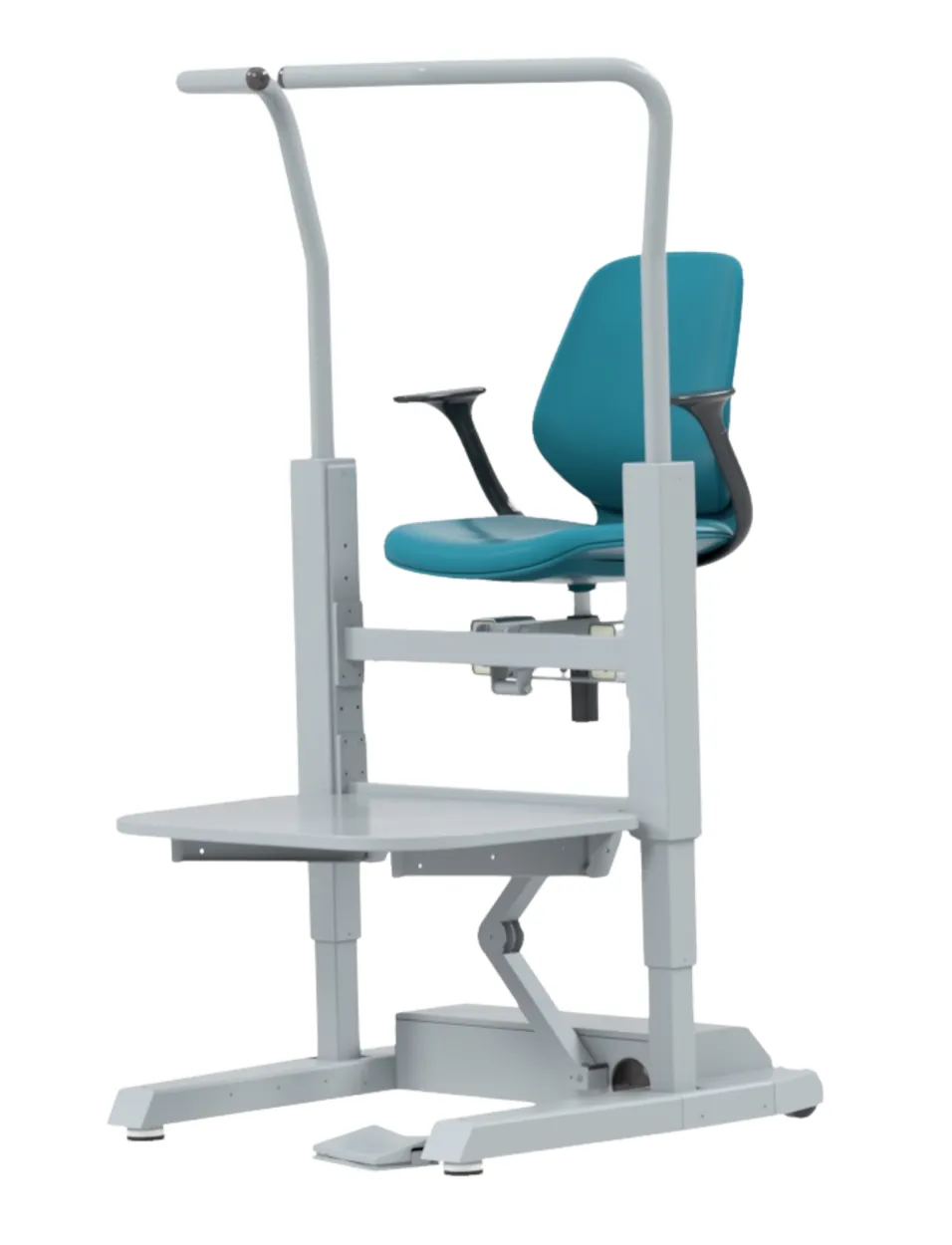
Orthostand M30 is an orthopedic lift that enables foot specialists to work more productively and comfortably while treating foot problems. The Orthostand M30 is equipped with a safe, electrically height-adjustable platform with a lowest step-up of 18 cm, rotating safety bars and seat safety bars.
The Orthostand M30 is powered by two motors. The system has a large lifting capacity, but is limited to 140 kg for safety, as heavier people may experience more balance problems.
Main parts & intended use
Main parts
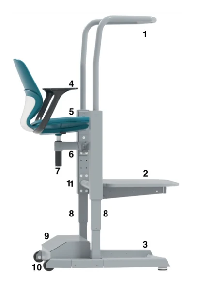
The numbered main parts (1–11).
Stand supports
Platform
Base
Seat safety supports
Seat
Seat frame
Gas lift
Lift units
Cable box
Wheels
Lower system frame
Intended use
Orthostand M30 is only suitable for the ergonomic measurement and fitting of footwear, prosthetics and orthotics by professional foot specialists, taking into account the stated maximum weights. Any further use is considered inappropriate. The manufacturer is not liable for any resulting damage; this is solely at the risk of the user.
The manufacturer does not take any responsibility for devices or mechanisms that are linked to the Orthostand M30 by third parties or foot specialists.
Warranty registration. Register the device with the manufacturer within three months after your purchase, using the QR code or NFC sticker. This includes uploading the purchase invoice to validate the warranty.
Safety requirements & operational guidelines
General safety & supervision
Minors: never leave children unattended with the system; they cannot properly assess the risks associated with the motorized power.
Maximum load: do not exceed the maximum platform capacity of 140 kg.
Prohibited use: no wheelchairs are permitted on the platform. Remote controls or memory functions enabling autonomous movement are strictly prohibited.
Control authority: the up/down console must be operated exclusively by the foot specialist; the client must never operate the controls.
The Orthostand M30 may only be used for vertical client transport. Horizontal transport of clients on the Orthostand M30 is not permitted.
Maintenance & technical integrity
Electrical safety: regularly inspect the 220 V power cable for damage. Ensure wheels do not roll over the power cable.
Emergency protocol: discontinue use immediately if smoke, odors, unusual noises or visible damage occur. Remove the plug from the socket.
Unauthorized access: never open system components. Electrical repairs and opening of modules are restricted to manufacturer personnel.
Liability & warranty: unauthorized modifications or improper repairs void the warranty and exclude the manufacturer from liability for resulting damages.
After 10 years, an inspection for possible wear and tear of parts must be carried out by the manufacturer or their authorized representative. The owner must take the initiative for this.
Responsibility of the owner
Prohibit the use of the device to all persons:
under the influence of narcotics, alcohol, etc.;
suffering from seizures, motor disturbances, vertigo, etc.
Responsibility of the foot specialist
The foot specialist must read and understand this manual and the labels affixed to the device, and must inform the owner of the absence or poor condition of the manual and labels and of all malfunctions and defects of the machine.
The specialist may only use the machine in the situations foreseen by the manufacturer, as described in the chapter Commissioning.
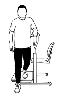
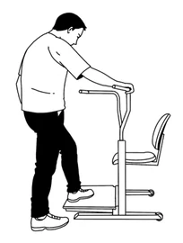
Less mobile clients must step onto the platform from the side, not the front. Open one rotating stand support sideways to facilitate safe access.
Ask clients whether they suffer from seizures, motor disturbances, vertigo, etc. The Orthostand M30 is not suitable for people with these risk factors.
Ensure both rotating stand supports are closed and fixed into their grid, and that the client is securely positioned, before elevating the platform.
Ensure no persons or animals (except the seated client) are within a 25 cm safety zone during downward movement.
To avoid crushing risks, never place your feet on the base of the Orthostand M30 construction during a moving operation.
Possible risks when working with the Orthostand M30
In the evaluation of possible risks when using the Orthostand M30, the following risks have been identified, together with the mitigation measures taken during development.
Risk: electrocution due to incorrect use of power
A standard electric cable from a wall socket is connected to the 220 V input of the control box via an IEC C14 chassis with a C13 cable connector mounted in the cable box. The cable exit from the cable box is fitted with a rubber grommet. All outputs of the control box are low-voltage (32 V DC) and safe to handle.
Risk: entrapment of the foot specialist's lower limbs
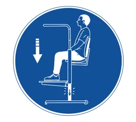
The client must sit during downward transport.
A hand or foot placed on the base of the lift could be pinched during the last part of the downward movement. The following mitigation measures have been taken:
Press-or-stop foot button: as soon as the foot specialist feels entrapment, releasing the button immediately stops the downward movement.
Hinged platform: greatly reduces the downward force. In the event of an obstacle the platform moves upwards; the downward force is then limited to a percentage of the residual weight of the seated client.
A sign states that the client must sit during downward transport, greatly reducing the downward force in the event of entrapment.
Remote controls or memory functions resulting in autonomous movement are prohibited.
The platform supports are placed far enough from the base, and the shapes of the platform supports and the sides of the base are partly rounded.
The Orthostand has a safety provision that stops the lift during vertical transport when entrapment is detected and moves it a few centimetres in the opposite direction. This also happens when a client moves strongly during travel.
Clients cannot operate the up/down foot switch when seated or standing on the Orthostand.
Do not load the platform with more than 140 kg.
The up/down speed is limited to 2.5 cm/sec.
Risk: falling when getting on or off the platform
Less mobile clients board from the side, using the handles.
Less mobile clients should step onto the platform from the side. The platform extends over the toes of the Orthostand M30 to reduce the risk of tripping and lower the step height when stepping on.
The solid stand supports rotate to fixation positions in lateral direction. The foot specialist must place the bracket in the correct position before and after getting on or off.
The step height is limited to 13.5 cm. The foot specialist must place the platform in the lowest position before boarding or alighting.
Risk: falling from the platform
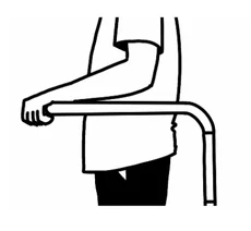
Standing clients hold the safety bars.
The solid stand supports are shaped around a standing person.
The stand supports have fixation positions in two more-or-less closed positions, depending on the posture of the client.
As an extra safety measure, a seat safety support is positioned on the sides of the seat to prevent falling sideways in a sitting position.
The height adjustment is limited to 50 cm.
Clients must hold the safety bars securely in the standing position.
Commissioning
To ensure optimal performance and longevity, the device must only be installed in dry, dust-free environments.
Room height requirements
The required ceiling height is determined by the system's vertical setting and the client's height. Please ensure the installation room meets the following minimum requirements:
System position
Step height
Max. platform height
Min. room height
Standard
18.5 cm
68.5 cm
264 cm
Middle
23.5 cm
73.5 cm
269 cm
High
28.5 cm
78.5 cm
274 cm
Max. client height = workspace height minus 69 cm (Standard), minus 74 cm (Middle) or minus 79 cm (High system position).
Initial setup & inspection
Use a spirit level to ensure the Orthostand M30 is level.
Inspect the device for any visible damage that could impede safe operation.
Inspect the power cable for defects, then connect it to the mains supply.
The frame and bases include provisions for future connection of third-party devices. For electrical connections, space has been reserved in the cable box for a socket; cables can be routed through the grommet via the optional elbow to the platform.
Directions for use
Operating the stand supports
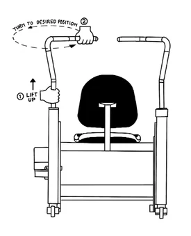
1. Lift up. 2. Turn to the desired position.
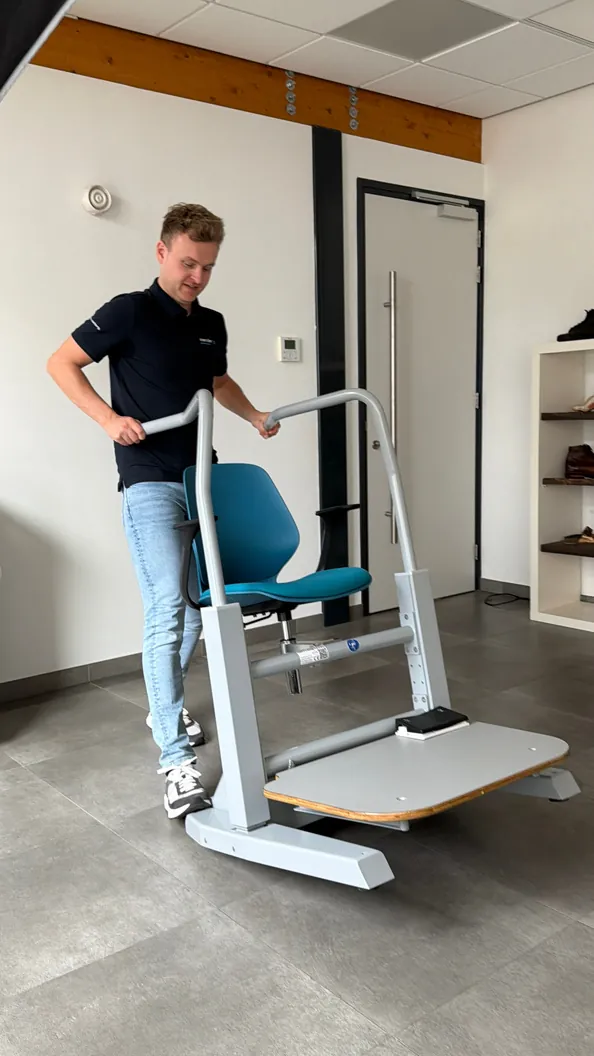
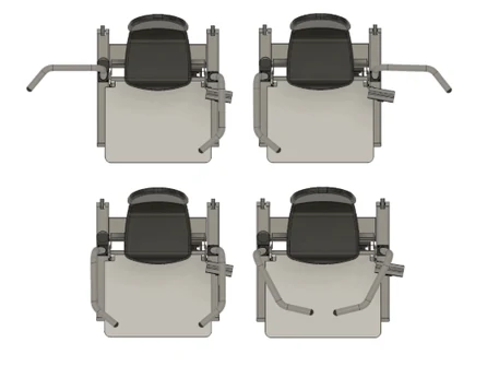
Take hold of a stand support under the first bend and pull it upwards to release the bar from its lock. The stand support can now rotate and be locked in three positions: Step Up, Large People or Closed. Always ensure the stand supports are locked.
The stand supports lock in different positions around the client.
When boarding, the platform safety support is open at a right angle as support for the client stepping onto the platform. After getting on, the client must first sit down to prevent possible entrapment of the foot specialist's limbs (less weight on the platform).
After boarding, close the bar in the most closed position possible (Closed, or the Tall People position). Make sure the bar is firmly secured in one of the three positions by feeling for the closing point while turning, then push the bracket down. Always recheck that the handle is locked in place before the client stands up.
Invite less mobile clients to pull themselves up on the handles for activities in a standing position.
Internal transport
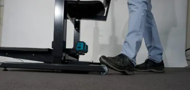
Press a foot on the rear wheel to tilt and move.
At the rear, two wheels are integrated in the lift module. The stand supports can be swung backwards and locked in the transport position. Press one foot on a wheel and the Orthostand M30 can be tilted back and moved. A minimum door width of 90 cm applies.
Attachments
Available attachments: Laser Bar, Leg Support or OrthoScan Plate.
Cleaning, care & disposal
Cleaning and care
The only thing that needs to be cleaned is the exterior surface of the lift. Do not use strong abrasives or solvent cleaners, as they may damage plastic parts.
Disposal considerations
The Orthostand M30 is designed to be recycled after its lifetime. Start by unplugging the power plug. Then unplug all cables from the control box (mounted in the electricity box with double-sided tape) and take out the control box.
The stand supports can be removed by loosening the four bolts in the nylon lift caps, then the bolts underneath; the stand supports can then be lifted off the rotating mechanisms. The nylon guides on the inside of the stand supports should be recycled separately. Remove the support legs at the front. Remove the wheels by loosening the bolts and recycle them separately. Remove the four bolts to detach the seat from the seat frame; the seat must be recycled separately.
If your country has legal regulations for the disposal of electrical and electronic equipment, the control box and actuators must not be disposed of with household waste; take them to a collection point for recycling of electrical and electronic equipment. By disposing of the product correctly, you help protect the environment and human health. For more information, contact your local municipality or waste collection service.
Troubleshooting
Anti-trap mode activates too often
The anti-trap function is a safety feature that stops the Orthostand during vertical movement and reverses it by a few centimetres when an obstruction is detected or when the client moves during travel. Possible causes and remedies:
The Orthostand is not installed level, check with a spirit level in both directions and adjust the feet if needed.
The control box is not properly secured, confirm it is fixed to the bottom of the cable box with double-sided tape or bolts.
The client is moving during travel, ask the client to sit still while the platform is raised or lowered.
The Orthostand M30 fails to move (up/down)
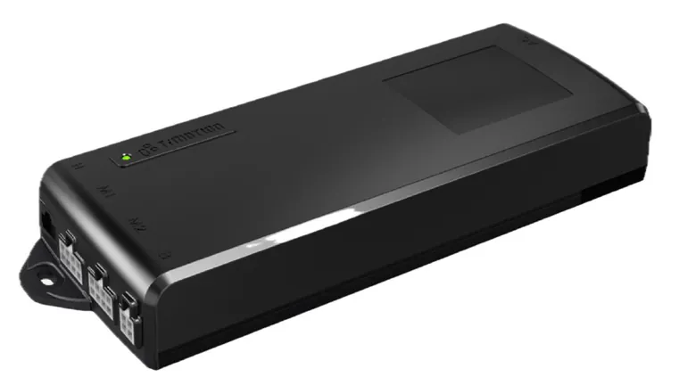
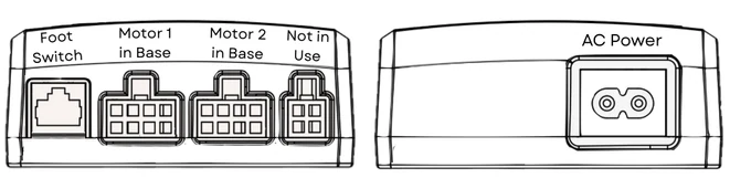
The control box in the cable box.Connections: foot switch, motor 1, motor 2, and AC power.
The most likely cause is that the plug of the foot switch is not fully inserted into the control box, as the foot switch cable is regularly pulled on. The foot switch must be connected on the right side of the unit (seen from the front). Open the electricity box at the rear of the Orthostand and check the following:
Test the wall outlet with another device to confirm it is supplying power.
Confirm the foot switch plug is fully inserted into the designated port on the control box.
Confirm the power cable is firmly seated in the wall outlet and the electricity box inlet.
Check that the C8 power plug is properly connected to the control box.
Power-off reset
Disconnect the power cable from the power inlet.
Wait for 30 seconds.
Reconnect the power cable.
System reset procedure
If the device remains unresponsive after the power-off reset:
Press and hold the Down pedal of the foot switch. The device will slowly descend to its lowest position and stop automatically.
Release the Down pedal.
Press and hold the Down pedal again for a few seconds, until you hear a beep from the control system in the cable box.
The reset is now complete.
After multiple failed resets
If the Orthostand remains unresponsive, the fault most likely lies with the control box (95%), the adapter, the foot switch or another cause. After contacting your supplier, replacing the control box may be the best solution. Replacement is straightforward and tool-free: remove the old box from the cable tray, plug the cables into the new unit, and fix the new box to the underside of the electricity box using double-sided tape.
Note: the control box is a relatively expensive part when out of warranty.
General specifications
Manufacturer
Ergonomix B.V.
Footprint
110 cm depth × 82 cm width
Platform
75 cm width × 52.5 cm depth
Seat
44 cm width × 47 cm depth
Seat height
42, 50 cm (adjustable)
Safety bars
110 cm above platform
Step-up height
18.5 cm (standard) / 23.5 cm (high)
Max. platform height
68.5 cm (standard) / 73.5 cm (high)
Lift travel
50 cm vertical electric lift
Net weight
75 kg
Max. load
140 kg (safety-limited)
Warranty
36 months limited warranty on the device; 24 months on platform, actuators, control box and cables, see the Terms & Conditions (art. 9)
Identification
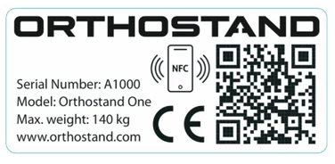
The machine plate (example) on the front of the chassis.
The machine plate on the front of the chassis identifies your machine: serial number (A-number), model and maximum user weight. Always quote the serial number when requesting information, support or repairs.
Scan the QR code, or tap your phone on the NFC symbol, to open your personal menu on portal.orthostand.com. It gives you three options:
Register your product: activates your warranty. Fill in the form; after a quick check we link your organisation to the serial number. Register as soon as you take the Orthostand into use and within three months of the invoice date.
Write a review: six short questions; we draft the review, you edit and approve it. Photos of your practice are welcome.
Something not working? The guided self-check solves most issues in minutes. If the problem remains, it prepares an e-mail with your serial number and a description of the situation, ready to send.
CE Declaration of Conformity
Manufacturer
Ergonomix B.V., also trading under the trade name Orthostand, Mevr. van Vollenhovenpark 11, 3971 CW Driebergen, the Netherlands
Generic name
Orthopedic lift
Function
Elevate the workplace for foot specialists
Trade and model
Orthostand M30, with the options: Sensor bar, Foot switch, FlexLeg support, OrthoScan
Product description
An electrically height-adjustable platform with standing safety supports and a height-adjustable seat that foot specialists use to treat clients with foot or leg problems
Serial number range
Series A10, A10.000
Ergonomix B.V. declares that the orthopedic lift Orthostand M30 complies with all applicable provisions of the Machinery Directive 2006/42/EC. This declaration relates only to the machine in the condition in which it was placed on the market, excluding components subsequently added and/or operations carried out by the end user.
Signed in Driebergen, 18 December 2025, Jan Beltman, Director, Ergonomix B.V. (also trading under the trade name Orthostand).
Harmonized standards and technical specifications
Reference standard
Subject
EN ISO 12100:2010
Safety of machinery, general design principles, risk assessment and risk reduction
EN 614:2006
Safety of machinery, ergonomic design principles
EN 894:2010
Safety of machinery, ergonomic requirements for the design of information and control
EN 1005:2008
Safety of machinery, human physical stress
EN 1037:2008
Safety of machinery, prevention of unintentional starting
EN ISO 13850:2008
Safety of machinery, emergency stop
EN ISO 13854:2019
Machinery safety, minimum distances to avoid crushing of human body parts
EN ISO 13857:2019
Safety of machinery, safety distances to prevent danger zones being reached by upper and lower limbs
EN ISO 14118:2018
Safety of machinery, prevention of unintentional starting
EN ISO 14122:2016
Safety of machinery, fixed means of access to machinery and industrial installations
The formal EU Declaration of Conformity is available on request: info@ergonomix.nl.